
 English
 العربية


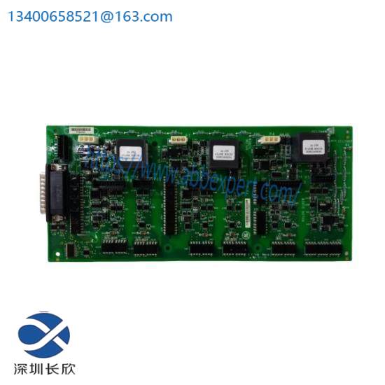
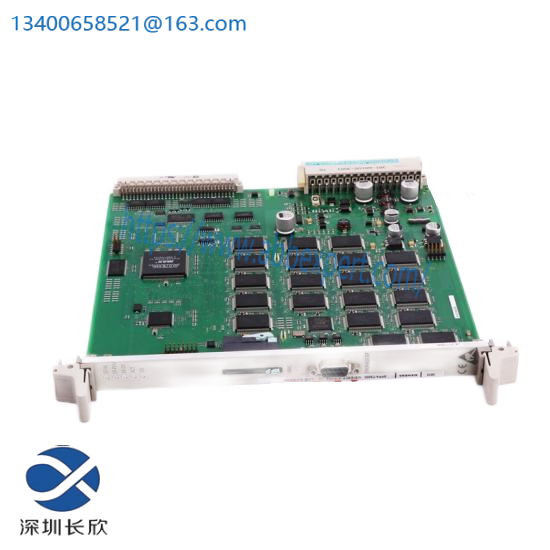
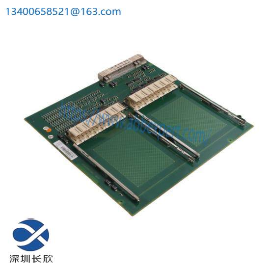


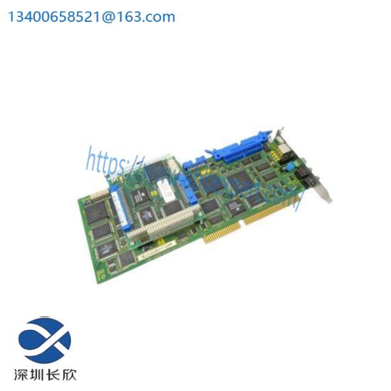
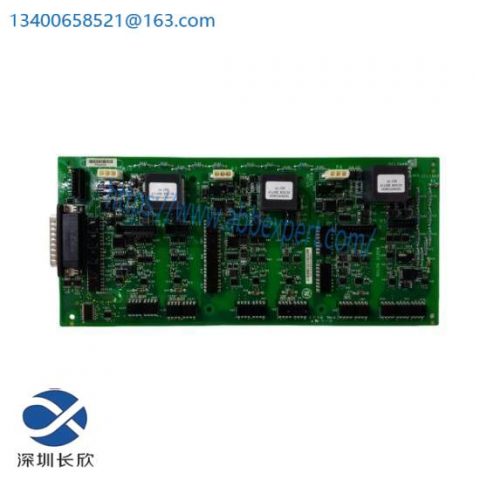
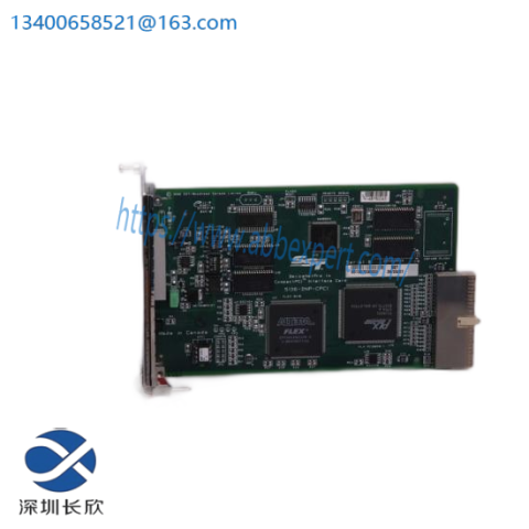
Belonging to the Advant/UNITROL excitation and power control series of Eurocard cards, this product is primarily used in generator excitation systems, high-power power converters, and AC800PEC controllers. It serves as a signal bridging and preprocessing interface board between the controller and power units, as well as external signals; it is not a general-purpose DCS I/O card.
Core Functions
1. High/Low Level Signal Isolation and Level Conversion
Achieves level matching and electrical isolation between the main control CPU’s low-voltage logic signals and power circuit/external field signals;
Isolates strong and weak currents, preventing power-side interference from entering the control motherboard and protecting the control core.
2. Analog and Pulse Signal Conditioning and Acquisition
Acquires power unit feedback signals: current, voltage, pulse speed measurement, and trigger synchronization signals;
Filters, amplifies, and divides the raw analog signals, converting them into standard levels recognizable by the controller;
Commonly used for preprocessing rotor current, stator voltage, and synchronization voltage signals in excitation systems.
3. Digital Control Pulse/Command Forwarding
Receives control commands from the main control board, driving power circuit triggering and switching output;
Uploads digital feedback signals such as power unit faults, temperature, and gate status to the controller;
Under certain operating conditions, it performs pulse distribution and synchronization signal shaping functions.
4. Hardware Fault Monitoring and Status Reporting
Real-time monitoring of onboard hardware circuits: signal disconnection, exceeding limits, and power supply abnormalities;
Panel LED status indicators, simultaneously uploading fault codes to the control system;
Supports online system diagnostics, facilitating fault location in the excitation/high-power drive system.
5. System Interface Expansion and Adaptation
Serves as an intermediate interface between different functional boards, simplifying internal cabinet wiring;
Commonly used in retrofitting older UNITROL excitation and high-power converters, achieving signal compatibility between new and old boards.
Typical Application Scenarios
ABB UNITROL Series Generator Excitation Control System (Most Popular Scenarios)
AC 800PEC High-Power Power Electronic Controller Interface
Signal Converter for High-Power Frequency Inverters and DC Drive Power Units
Control Cabinets for High-Power Drive Equipment in Power Plants and Metallurgy
Key Features
European Standard Plug-in Structure with Backplane Bus Connection;
High-voltage/Low-voltage Separation Design, Resistant to Industrial Electromagnetic Interference;
No Independent Program, a Hardware Signal Pre-processing Interface Card, Relying on Main Control Board Logic for Operation;
I. Pre-Installation Preparation (Crucial)
Safe Power Off: Disconnect all power supplies to the entire excitation control cabinet and plug-in boxes, and sign a power outage notice; use a multimeter to confirm that there is no voltage on the backplane bus and external high and low voltage circuits.
The does not support hot-swapping; hot-swapping can easily damage the backplane bus and board chips.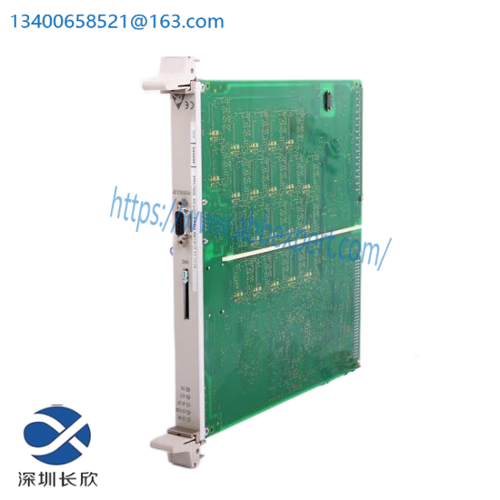
Anti-static Measures (Mandatory)
Wear a grounded anti-static wrist strap, reliably grounded;
Keep the anti-static bag when removing circuit boards. Do not touch circuit board components or gold fingers with your hands;
Do not handle bare boards directly in dry environments or in environments where synthetic clothing is worn.
Material Verification
Complete model: version number consistent with the original spare part;
Inspect gold fingers for oxidation, dents, and bent leads; check circuit boards for bulging capacitors.
Environmental Inspection: The cabinet interior is free of dust and condensation; the mounting rails and backplane connectors are free of rust and metal debris.
II. Mechanical Insertion Installation Procedure (Eurocard European-style Card)
Remove the front cover of the slot (if existing);
Align the upper and lower guide slots of the module with the card’s guide rails and push it in smoothly and horizontally;
Push inwards at a steady speed until the rear gold fingers fully engage with the backplane connector; ⚠️ Do not push forcefully if you encounter resistance! Check for misalignment of the guide slots and bending of the backplane pins.
Tighten the two M4 fixing screws on the top and bottom of the panel with moderate force (0.8~1.0 N・m) to prevent loosening due to vibration;
Confirm that the card panel is flush with other cards and there are no warped edges.
Structural Description: The is a standard Eurocard 3U European-style card, communicating via the rear backplane bus. External signals are led out through the panel terminals/aviation connector.
III. Jumper Settings and Hardware Configuration (Must be verified when replacing spare parts)
Compare with the old board and record the position of each onboard jumper cap;
The new board’s jumper settings are a complete replica of the original configuration; incorrect jumper settings will result in: abnormal signals, inaccurate data acquisition, and bus communication failure;
This card has no hardware address DIP switches; the address is determined by the slot location and controller software configuration.
IV. External Signal Wiring Specifications
Distinguish between cable types:
Analog feedback signals (voltage, current, synchronous sampling): Shielded twisted pair;
Pulse/trigger signals, digital switch signals: Shielded cable;
Shielding treatment: Single-end grounding (grounded at the cabinet grounding bar, the far end left floating) to avoid ground loops and interference;
Separate high-voltage and low-voltage cables: Power circuit cables and signal cables should be laid in separate channels;
Strictly follow the terminal numbers in the schematic diagram to prevent high voltage from entering the signal circuit and burning out the module.
V. Pre-Power-On Checklist
All terminal connections are secure, with no loose connections or short circuits;
Backplate is properly inserted and screws are tightened;
Jump wires are consistent with the original board;
No residual wires or metal debris inside the cabinet;
Grounding system is intact, and the cabinet’s protective grounding is reliable.
VI. Power-On Debugging Procedure
First, supply control power; do not immediately engage the excitation main circuit;
Observe the LED indicators on the panel:
Power indicator is constantly on;Fault indicator has no red alarm;
Log in to the host computer/excitation controller and check the hardware diagnostics: Identify the module, no bus fault;
Verify that all analog signal acquisition and feedback values are normal;
No-load test: Confirm there are no signal disconnections, triggering anomalies, or excitation-related alarms;
Load test run: Continuously monitor module diagnostic information.
VII. Important Prohibitions and Common Mistakes
❌ Do not hot-plug modules.
❌ Do not touch the circuit board directly without wearing an anti-static wrist strap.
❌ Do not forcefully push the card, causing the pins of the back panel socket to bend.
❌ Do not power on boards with inconsistent jumper settings.
❌ Do not ground the shielding layer at both ends, causing interference and signal drift.
❌ Do not interchange slots for different card models (CSA463AE).
VIII. Reverse Disassembly Procedure (Reference for Spare Parts Replacement)
Completely power off and test the system for voltage.
Disconnect the external signal cables from the panel.
Loosen the panel fixing screws.
Grasp the panel with both hands and slowly pull it outwards in a straight line. Do not pry from one side.
Recommended related products:
V4561983-0100 ALSTOM
L54E1100CZ00 CPRM1 ALSTOM
L54E2900WB00 BCEL2 ALSTOM
L54E2900WF00 CSR1 ALSTOM
MMLG01 ALSTOM
EP3-E-4-A ALSTOM
V4550220-EN ALSTOM
KCEU142 ALSTOM
I/OBE2 12004-104-00 V1.0.0 ALSTOM
V4555724-0100 ALSTOM
AH116-2 ALSTOM
AS111-1 ALSTOM
AB121 ALSTOM
AL132 AL132A STO0982E01
UT150-1 ALSTOM
LE109A-1 ALSTOM
AM164 ALSTOM
IR139-1 ALSTOM
P40 AGILE MICOM P141 ALSTOM
AL132 ALSTOM
More……

There are no reviews yet.